The main components of programmable logic controllers are similar to those found in personal computers. Basic PLC hardware consists of a central processing unit (CPU), RAM and ROM memory, power modules, Input and Output modules and an interface module (or some output that can connect to an external interface module). Depending upon the PLC model or function, the I/O modules can include discrete (on/off) or analogue signals. Unlike a PC, however, the hardware in a PLC is package to withstand the conditions usually found in industrial environments.
Modern PLCs can include these modules in one package, usually with a small number of I/O.
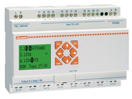
LOVATO Electric Kinco Micro PLC
Larger PLCs have their I/O modules separate from the CPU unit. These modular PLCs, usually rack based have the ability to add/remove I/O modules to expand the number of controls as needed.
CPU
Much like a central processing unit in a personal computer, the CPU is a microprocessor capable of performing the calculations and operations needed to run the PLC. Usually the CPU, and the clock within it, determines the operating speed of the PLC. The execution time of each instruction code takes a specific number of clock cycles. A CPU with a 10 MHz clock will execute a line of code in 0.1 µs (Crispin, 1997).
BUS
Again, much like a personal computer, information is transferred via several buses. The CPU uses the data bus to data between each of the various PLC components; the address bus to send the addresses of locations of stored data; the control bus for signal relating to internal control actions. Communications between I/O ports is done using the system bus (Bolton, 2009).
Memory
Read only memory (ROM) is the permanent system storage which the PLC operating system and fixed data is stored.
Random Access Memory (RAM) is rewritable and is used to store the user’s program as well as data involved in the current program processes, such as timer values and counters etc.
Input/Outputs
The I/Os provide the means for the PLC to communicate to the outside world and typically consist of sensors, motors and solenoids (Bolton, 2009). The logic code provided by the user will determine how the PLC operates the outputs depending upon the input signals provided to the PLC.
Input interfaces can include: DC and AC, pulse counters, Analogue to Digital interface
Output interfaces can include: Relay outputs, transistor outputs, triac outputs (able to control external AC circuitry), Digital to Analogue interface (Crispin, 1997).
References
Bolton, W. (2009). Programmable logic controllers. Oxford: Newnes.
Crispin, A. (1997). Programmable logic controllers and their engineering applications. London: McGraw-Hill.
Micro PLC with RS485 built-in | Lovato Electric. (2016). Micro PLC with RS485 built-in | Lovato Electric. [online] Available at: http://www.lovato.co.uk/Micro%20PLC%20with%20RS485%20built-in/884/2954/sn [Accessed 12 Mar. 2016].

I have done training on plc(mitsubishi) Q series and D inverter700 from training i understood that future is PLC technology and am happy you r writing on this topic
LikeLiked by 1 person
like my blog also…give your thoughts
LikeLike